
Timetable
[No Longer In Production]
(Clock Divider / Pattern Generator / Sub-Oscillator)
The Pittsburgh Modular Timetable module isa Clock Divider / Pattern & CV Generator. The primary intention of Timetable is to provide timed gates, both predictable and inconsistent. In practice, you can use the module as a straightforward clock divider and pattern generator or as a hyperactive gate and CV spewing lunatic… and of course something, somewhere in the middle. A binary system that sometimes gets stuck somewhere between 1 and 0.
The output of the Timetable is split into two distinct sections. The first section is a clock divider that produces straight quarter, half, whole & double whole-note divisions of the input signal. The patterns generated in the second section range from a replica of the first section to complex patterns tied to several factors such as CV, user interface settings and the logic chip installed.
Here is some audio of the Timetable in action. A basic oscillator and filter are used with the Timetable in this demo. The pitch of the oscillator, frequency of the filter, and the divider within the Timetable are all CV’d from different voltages available on the Timetable.
Even in its basic configuration the Timetable is ‘bent by design’ it takes advantage of what could (should?) be considered errors to provide variations and unpredictable (but not random or chaotic) changes… all tied to a clock. The user can also take the ‘bends’ further by swapping out one, or both, of the CMOS logic chips in the core of the circuit. Changing the logic chip changes the functionality of the Timetable creating a new set of behaviors to explore.

A Mod Pack is available separately so it will be easy to try different combinations of logic. It comes with 2 sets of 4 different logic chips, a logic pattern table for each chip, an IC Remover to make swapping out chips a breeze, a sticker, a fancy cardboard box with anti-static foam to keep everything safe, and a secret prize. The mod pack will be $15 USD. The logic chips included in the Mod Pack are NOR, NAND, XOR, XNOR.
A More Detailed Description…
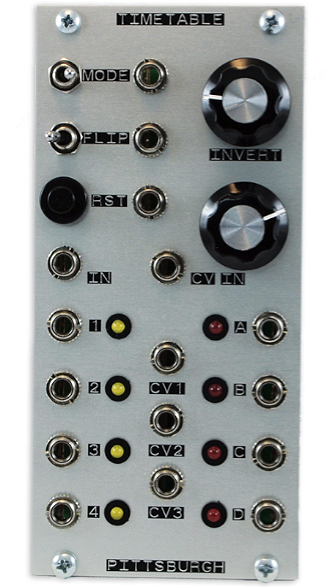
Divider 1:Divider 1 (outputs 1/2/3/4) produces fixed /2, /4, /8, /16 clock divisions. These outputs are not effected by any of the CV or external controls, it is the straight guy.
Divider 2:Divider 2 (outputs A/B/C/D) starts from the same point as Divider 1 but the counter can be manipulated in a number of ways…
Mode:Divider 2 can be advanced by either the main clock, or the last stage of Divider 1. With no CV and the Invert control fully counter-clockwise this just extends the count for longer divisions. The Mode can be controlled by external gates.
Flip:Flip turns Clock Divider 2 into a simple type of A/D Converter or Waveform Follower. WIth this setting Clock Divider 2 follows the waverform of the Flip CV Input or if the Flip CV Input is not patched, the waveform of CV Output 1.
Invert and CV Input:The voltage of the CV Input is added to the Invert voltage based on the setting of the CV Input / Feedback Knob. The CV Input is normaled to the output of CV1 so when nothing is patched into the CV Input an internal feedback loop is created.
Gate Inputs:All the gate inputs have a threshold of ~1V.
Gate Outputs:The gate outputs (1/2/3/4 and A/B/C/D) follow the pulsewidth of the clock. With some feedback patches its possible to get triggers from A/B/C/D with “gate” inputs.
CV1 – 3 Outputs:These are voltages derived from Divider 2. CV1 is stepped, bipolar and CV3 is stepped, unipolar. CV2 is the smoothed difference between CV1 and CV2. In use CV1 and CV2 are useful for things like filter sweeps etc… CV3 is great for pinging filters and Low Pass Gates. All 3 CV outputs are great for controlling VCOs.
Usage Notes:1. Using a fast LFO into the CV Input, you can get bursts of events that only occur when the clock is high.
2. Both sets of divided outputs (1/2/3/4 and A/B/C/D) are generated the same way, by first ANDing the clock with the output of a binary counter. A/B/C/D has the voltage controlled logic applied to the binary outputs before the AND.
3. One cool patch is to control Flip with output 3 or 4. This starts both dividers from the same point but as they advance they get offset, then eventually after a fairly long cycle, they come back into alignment. SImilar to the effect of singing in the round ,but for the chorus everyone sings at the same time.
4. Another interesting patch is with the Mode switch up and the Invert pot fully clockwise. The A/B/C/D outs will now follow the clock, but for every 16 clock pulses a different set of outs will be active. If the outputs were clocking sequencers you have a kind of “dueling banjos” set-up.
Size: 12hp
Depth 50mm
Power Usage: 30mA
Timetable manual available in .pdf format by clicking on the image below.
The Timetable circuit was designed by Thomas O’Connor.